[email protected]
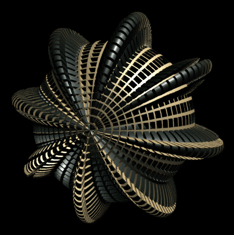
To define the 'grate' that is used in this displacement/surface shader,
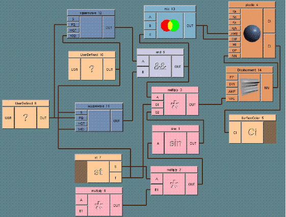
s & t are each passed to a squarewave generator. The outputs
are combined by a logical and, which returns a '1' when we
are inside one of the 'black square' regions, and a '0' when we are
outside.
This 0/1 output from the logical and is used to determine both
color and displacement; it's fed into mix, which chooses the
'A' color when the value is 0 (the tan color), and the 'B' color when
1 (black). It's also fed to the input of a multiply to switch
the output of a sine wave on and off; on when we are in the black square
region (1) and off (0) when we are outside. This means the sinewave
displacement (which itself varies between -1 and 1) is applied only
to the black regions, displacing micropolygons away from the sphere's
surface when 1, and displacing them BELOW the sphere surface when -1.
The displacement box's AMP (amplitude) input changes the scale
of the displacement, allowing one to effectively control the height of
the sine wave displacement.
The sine wave is generated by a scaled version of the sphere's 's' value;
s is multiplied by 360, and then by a frequency count, which determines
the number of sine wave periods that occur when the original 's' value
walks from 0 to 1. In this case, the frequency is set to 8, to give
the 8 sine wave 'bumps'. The overall displacement is also scaled at the
so the displacement ramps down to 0 at the poles.
There is a problem with using squarewaves, though; since the edges of the
wave are infinitely sharp, you will get aliasing problems at the edges of
the displacement. It is usually better in practice to create slightly soft
edges, so that the displacement 'ramps' a little bit, to prevent aliasing.
Here's the desktop for the above image:


Copyright (c) 1996 Cinema Graphics Inc. All Rights reserved.


